Is your netbookenvious of touch-driven devices? You can’t turn your netbook into an iPad, but you can retrofit it with a touchscreen and avoid the tiny touchpad.
WARNING: Only skilled or daring hardware hackers should attempt this process. Voiding the warranty is the least of your concerns; you’ll have to solder parts together, cut away some of the laptop’s plastic housing, and otherwise make permanent changes that you can’t undo. Make the wrong move, and you’ll break the laptop. We are not responsible for anything that goes wrong with your PC as a result of your following our instructions.
If you know your way around a soldering iron and are willing to strip your netbook down to its last screws, however, you’ll likely succeed at this project. It’s a straightforward process, even though it’s too daunting for beginners.
I installed a touchscreen into a Dell Mini 10. Follow my steps if you have that exact netbook, or read through to get a sense for how to approach your own model. The general process will be the same, and I include many tips that I picked up along the way. Read through to the end before getting started.
Tool Time
First, line up all the parts and tools you’ll need to install a touchscreen.
Of course, the touchscreen panel itself is the centerpiece. This clear overlay sits on top of your current LCD. Usually it’s sold in a kit with a USB controller board. I couldn’t locate any shops that keep these in stock, so I turned to eBay and a Hong Kong importer.
Pick a touchscreen panel that matches the size and aspect ratio of your screen. I bought a 10.1-inch model that fits the Mini but was designed for an Acer Aspire One, for $90. These panels are usually resistive–that is, responding to pressure–not the capacitive type, which recognizes your skin. Single-touch panels are also more common; get a capacitive, multitouch panel if you can find one, but prepare to pay more.
You’ll also need a reliable soldering station. I have the Weller WES51. I can set its temperature to make it hot enough to melt solder without sending excessive heat to the connected parts.
Get a small tip or two for your soldering iron. I have 1/32-inch and 1/64-inch tips. You’ll make small joints and surface-mount connections that require a fine point. Also, use some fine solder, with about a 0.02-inch diameter. You’ll need to add your own flux, as well; I just brush some on from a jar, but pick whatever kind you like.
You might need some low-gauge wires to extend the touchscreen cabling. If you have a spare USB cable, cut that open to harvest its wires.
If you have the motor control and eyes of a 14-year-old, you might be able to work without magnification. Otherwise, I recommend a lighted, magnifying arm. Buy one from an electronics-parts store such as Jameco, or even from Amazon.
Also, you’ll need a Dremel or similar tool to shave plastic from one of the speakers and to lop off a leg under the wrist rest.
Finally, gather the basics: a pair of scissors or a wire stripper, electrical tape, a Phillips screwdriver, and other common tools. Grab a handful of guitar picks to help crack open the case, and tweezers to make fine movements. Also keep a days-of-the-week pillbox or two to store screws in separate compartments. Put the screws from each step in their own compartment, and write down where you stored them as you progress.
Get Hacking
Clear off a well-lit workspace, and you can begin the dissection. First, unplug the laptop and remove the battery. Turn the machine upside down on a padded surface to avoid scratches; a big mouse pad works well. Remove the four screws on the corners surrounding the battery cavity.
With that battery slot on the edge away from you, remove the four screws along the edge closest to you. Each set of those screws straddles one of the two rubber footpads.
Remove the screw in the center of the laptop. If this screw doesn’t fall out, you can push it out after removing the keyboard in the next step.
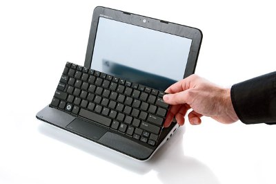
Turn the laptop right side up, and open the screen. Lift the keyboard out from the top edge, along the F-keys. Pivot it over the spacebar edge to access the ribbon cable underneath. Use your fingernails, tweezers, or the dull side of a hobby knife to slide back the tabs next to the ribbon cable; once you’ve moved those, the cable will be released. Set the keyboard aside.
Remove the metal RAM cover on the right. The captive screw should stay with that plate.
Remove the remaining hard-drive screw. Slide the drive to the left to unseat it from the SATA port. Remove the drive.
Within the keyboard cavity, remove the screw from the lower-left hole and the two screws on the lower edge on the right. The latter two sit on either side of the RAM. All of those screw holes are marked ‘M2.5X5’.
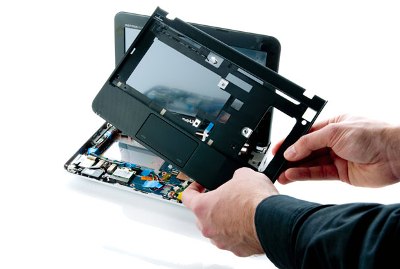
Above the touchpad, remove the cable inside of the rectangular hole in the plastic. Gently lift up on the connector tab, again with a tool or fingernail, to release the cable.
Unplug the power-button cable at the top, middle of the case. Be careful to separate the cable plug from its socket. Instead of yanking on the wire, try to separate those two parts with tweezers or the dull edge of a hobby knife; they fit tightly.
On the display, use a hobby knife to pry off the rubber adhesive feet on the lower corners. Store those pads in the pillbox or somewhere else for later. Remove the two exposed screws.
Separate the front of the display housing from the back. Use guitar picks again, and gently work from the inside of the screen for better leverage. Avoid scraping the screen; lift the housing up slightly, and pry inside to release it.
Returning to the base of the laptop, near the front, remove the screw from the upper-left part of the Wi-Fi card. The card will pop out the way RAM does. It will still be attached to its two wires. Remove the card and set it to the left side of your workspace; loosen those wires from their tape and tabs as needed, but leave them attached.
Remove the thick socket cable at the top-right side of the motherboard that leads to the display. Carefully separate it by pushing the edges with tweezers or another fine tip.
For this next step, you’ll want to keep the display at 90 degrees, because you’re going to remove the display and its connected housing now. Remove the three hinge screws that mount to the base, next to the motherboard. One is on the top-left side, in the general area of the VGA port, another is on the top-right side with an attached grounding loop wire, and the last is behind the display on the back-right corner.
As you remove the screws, keep one hand propping up the display so that it doesn’t fall. Once the display is free, set it behind the base of the laptop, as if you were opening it 180 degrees.
Remove the screw on the left of the base, generally near the USB ports. It’s marked ‘M2.5X5’. Remove the gray housing part that you just freed underneath.
Detach the flat, black ribbon cable from the lower left of the base by gently lifting and tilting the black tab in the socket. Use tweezers or other tools as needed. Lift the cable straight up.
Detach the cable connecting the main motherboard with the secondary circuit board on the left side of the base. This junction is next to the previous cable, and your target is the socket with the snarled, individual wires. Remove the screw underneath that cable.
Solder to the Netbook
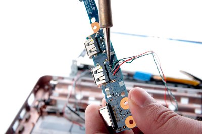
Lift out the L-shaped board that holds the two USB ports, flash card slot, and VGA port. This is our target point to solder the touchscreen controller board cable to the laptop.
I first tried to desolder one of the USB ports, remove it, and connect the new cable with simple through-hole soldering. However, not only was I not able to free the USB port, but I also ended up damaging the board in my attempt.
Instead, I recommend surface-mount soldering to the back of that board. It’s not as elegant, but it’s simpler and should work just as well. Since my touchscreen kit included cables for an Acer PC, I cut one of them about three-fourths along its length. I then soldered the longer piece to the board.

Spread some flux on the target pins; you’re aiming for the four positioned directly behind the USB plug. With the board upside down and the plug facing away from you, solder the pins from left to right with the respective colors: red, white, green, and black. Connect the wires to the rightmost USB port, the one near the VGA port.
Strip just enough of the wire ends to expose them before soldering. Heat up the wire with the soldering iron, and melt a little solder directly onto the iron. This is normally bad form, but you’re going to hold the wire directly on its target and carry the solder over. It should flow to the wire and board.
This process should just take a few seconds per pin. I prefer to hold the wire with tweezers to keep my fingers away from the heat.
Let the wires cool for a minute, and then turn the board over. Cut the four pins on the soldered USB port, severing them as close to the board as possible.
At this point, you’ve rerouted one of the USB ports to the touchscreen controller board and disabled the actual port. However, you can rewire the port to a hub built into the touchscreen controller. I didn’t make that connection, because it can be hard to reach those pins you just cut, but here’s how.
Solder an additional segment of cable to the short set of wires, extending the attached plug’s reach. The finished length should be about the same as the other wires soldered to the netbook’s USB port.
With the same surface-mount soldering technique–flux first, then carry over the solder–connect the four wires. With the USB port facing away from you, from left to right the colors should be black, green, white, and red. Avoid shorting out those cables between one another or bridging back to the circuit board.
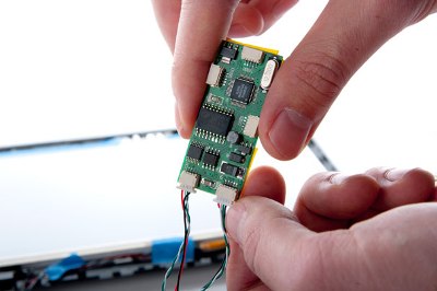
Plug the first cable into the USB In on the controller board. If you’re restoring that USB port, plug the second cable into the USB 1 port.
Reattach the USB board, including its screw and two cables. Reattach the long gray part directly above.
Mount the Touchscreen
Now you’re going to attach the touchscreen. Since any dust or fingerprints between the LCD and touchscreen will stay forever, I recommend wearing nonpowdered latex or vinyl gloves. At the very least, use screen cleaner on the LCD before continuing.
Remove the covering from the touchscreen part, and attach it so that it evenly surrounds the LCD. Position the ribbon cable on the right side. (Your specific screen part might vary.) Affix it with a thin, sparing layer of single- or double-sided tape. Gently bend the ribbon cable over, creating a 90-degree angle, leading to the lower-left corner of the display. Tape it loosely in place.
Connect the ribbon cable to the socket extender. Tape that loosely in place, running to the left corner of the screen. Connect it to the Touch port on the controller card.
Reattach the hinge and LCD screen to the base of the computer using the three screws. Route the cables through the hinges as they were originally wired, keeping them in the open end to avoid pinching. Reattach the right cables, including the grounding loop inside the screw.
Clear Space for the Controller
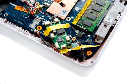
The touchscreen controller card doesn’t take much space, but jamming it into the tight case is tough. I almost fit it underneath everything, but it slightly bowed the motherboard; tighten the screws too much, and I would have cracked something. Instead, I made room by cutting away the right speaker and a plastic tab above.
Grab the big plastic part that contains the touchpad, and use a Dremel or other tool to cut the tab on the back of the right side of the wrist rest. (When working with the part, you’ll turn it over, so it’ll be on the left.) Cut off as much as you can, but you don’t need to obsess.
Cut the right speaker wire halfway between the speaker and the plug, and solder a 3-inch wire extension to one of the sides. Unscrew the speaker. Before you take the speaker all the way out, you’ll notice that the speaker part favors the left side of its black, plastic enclosure. You’re going to cut the right side away.
Working with a Dremel or other cutting tool on a medium speed, carefully start by cutting plastic back on the long, corner edge farthest away from the speaker part. Make a careful incision to affect just the top of the plastic, and pry it up.
You’ll now see the metal speaker inside and the internal wire positions. Cut away as much of the plastic next to the speaker part as possible, including one of the screw mounts. Avoid the wires.
Resolder the speaker back to the wire. Screw and tape the speaker into position in the rightmost screw hole, facing down. The touchscreen controller will sit over the motherboard and the gap where the speaker had originally been.
Line the back of the controller with electrical tape to protect it from scuffs and prevent an (unlikely) short circuit. Position the controller board rotated slightly clockwise, with one corner well over the gap you created. The top corner should nestle closely to the bottom heat-sink screw and avoid screw holes on the motherboard. Also avoid the white dot above the original speaker position; the upper case rests here.
Tape the touchscreen controller in place. Reattach the Wi-Fi card, and run its wires back in the original path. Tape the touchscreen wires in place in the same channel or in the edge of the hard-drive cavity. (The hard drive will fit tighter if you do this, but there’s just enough room.) Make sure you don’t cover any screw holes.
Feel the Difference
Now it’s time to put your baby back together. Reattach the LCD bezel and the plastic layer that contains the touchpad, connecting that ribbon cable and connecting the power-button cable near the top. Reattach the hard disk and RAM cover. Replace the screws along the way.
You did it! Windows 7will automatically recognize the touchscreen, and you can calibrate it in the Control Panel. Your netbook might not look any different from the outside, but you’ve extended its life and given it an interface upgrade.
Source: PCWorld


